Contaminants removed utilizing Amine Treating
- CO2 – Carbon Dioxide
- H2S – Hydrogen Sulfide
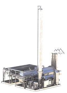
Amine treating plants remove CO2 (carbon dioxide) and H2S (hydrogen sulfide) from natural gas. Amine has a natural affinity for both CO2 and H2S allowing this to be a very efficient and effective removal process. Newpoint’s proprietary amine plant design is based on proven amine regeneration technology and incorporates several patent-pending processes to improve the reliability and ease of operation.
 Benefits of Amine Units
- Reduces CO2 and H2S levels to the required specifications
- Modular, skid-mounted systems
- Reduced manufacturing and commissioning times
- Standardized and proven designs
- New equipment only
- Guaranteed performance
- Lower installation and removal costs
- Built in liquid containment to reduce environmental hazards
Shortest Lead Time Possible
To meet the growing demands of industry, Newpoint made the bold decision in 2005 to standardize their designs, to build equipment on speculation, and have plants ready for immediate delivery. In 2006 and 2007, Newpoint further optimized these units and reduced equipment commissioning times by 50%.
Reasons for Removing CO2 and H2S
Carbon dioxide, hydrogen sulfide, and other contaminants are often found in natural gas streams. CO2 when combined with water creates carbonic acid which is corrosive. CO2 also reduces the BTU value of gas and in concentrations of more that 2% or 3 % the gas is unmarketable. H2S is an extremely toxic gas that is also tremendously corrosive to equipment. Amine sweetening processes remove these contaminants so that the gas is marketable and suitable for transportation.
Companies around the world have found Newpoint’s proprietary design to be the perfect fit for their gas treating applications.
Amine Gas Sweetening Solutions
Amine gas sweetening is a proven technology that removes H2S and CO2 from natural gas and liquid hydrocarbon streams through absorption and chemical reaction. Each of the amines offers distinct advantages to specific treating problems.
- MEA (Monoethanolamine)
- Used in low pressure natural gas treatment applications requiring stringent outlet gas specifications
- MDEA (Methyldiethanolamine)
- Has a higher affinity for H2S than CO2 which allows some CO2 “slip” while retaining H2S removal capabilities.
- DEA (Diethanolamine)
- Used in medium to high pressure treating
- does not require reclaiming, as do MEA and DGA systems.
- FORMULATED (SPECIALTY) SOLVENTS
- A variety of blended or specialty solvents are available on the market.
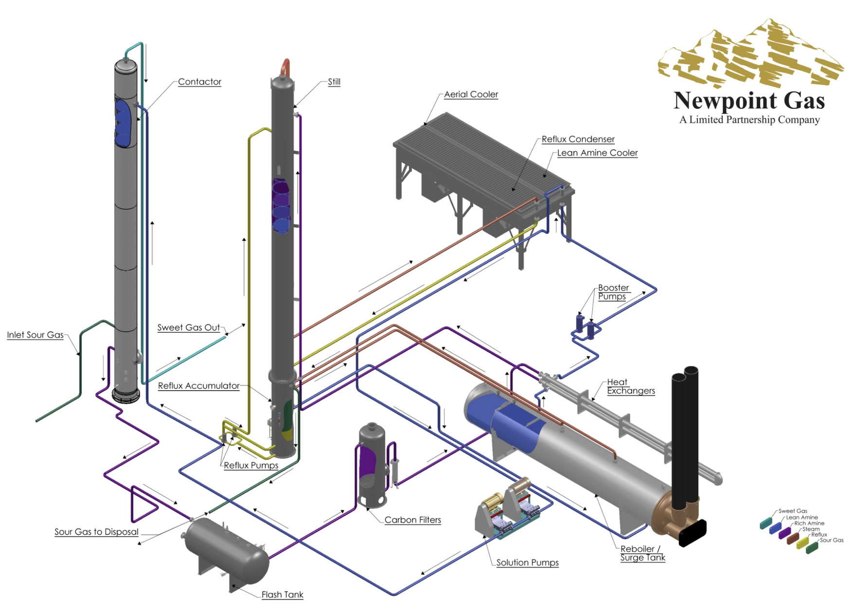
Typical Amine Systems Flow Diagram

Amine Gas Sweetening Process
- Sour gas enters the contactor tower and rises through the descending amine.
- Purified gas flows from the top of the tower.
- The amine solution is now considered Rich and is carrying absorbed acid gases.
- The Lean amine and Rich amine flow through the heat exchanger, heating the Rich amine.
- Rich amine is then further heated in the regeneration still column by heat supplied from thereboiler. The steam rising through the still liberates H2S and CO2, regenerating the amine.
- Steam and acid gases separated from the rich amine are condensed and cooled.
- The condensed water is separated in the reflux accumulator and returned to the still.
- Hot, regenerated, lean amine is cooled in a solvent aerial cooler and circulated to the contactor tower, completing the cycle.
Typical Amine Plant Standard Features
- 100% Pump Standby
- ASME Code and National Registration on all vessels
- Shell and Tube or Plate Frame Heat Exchangers
- B31.3 compliant piping
- Total Custom Electrical Systems and Instrumentation
- Full Flow Carbon Filtration
- Engineered Corrosion Control
- Spill & Leak Containment
- Multiple patents-pending to enhance ease of operation and maintenance
- Modular design eases installation time and cost
- High Efficiency Reboilers

